DIY kit - LED clock


This page explains how to assemble and solder the DIY LED clock. Each building step is thoroughly explained and the important parts are highlighted. After this guide you should have a fully functioning and fun LED clock!
Table of contents
1. Requirements
- Soldering station, for example the Atten AT937.
- Soldering tin, for example the lead-free soldering tin 1mm.
- Cutting pliers, for example the VT281.
- Tin extractor, for fixing small mistakes
- PH0 screwdriver, for assembling the case
- 1x CR1220 battery
2. Component list
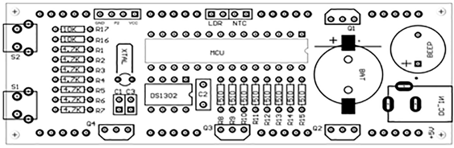
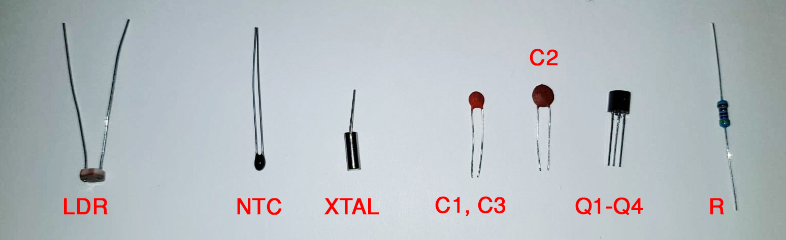
| Component | Information | Component | Information |
| R8-R15 | Resistor 510 Ω | R1-R7 | Resistor 4,7 KΩ |
| R16, R17 | Resistor 10 KΩ | C2 | Capacitor 104 |
| C1, C3 | Capacitor 22P | Q1-Q4 | Transistor S8550 |
| NTC | Temperature dependent resistor | U1 | Clock IC DS1302 |
| LDR | Light dependent resistor | MCU | Microcontroller |
| BAT | Battery holder | XTAL | Crystal oscillator |
| S1, S2 | Push button | BEEP | 5V buzzer |
| DC-IN | Power input |


3. Assembly instructions
3.1 Resistors
Each resistor has a different value, which can be identified by the colored rings on the resistor itself. Make sure you use the correct resistors in the right spot!| # | Resistor | Color code | Amount |
| 1 | Resistor 10 KΩ | Brown black black red brown | 3, 1 spare |
| 2 | Resistor 510 Ω | Green brown black black brown | 9, 1 spare |
| 3 | Resistor 4,7 KΩ | Yellow purple black brown brown | 8, 1 spare |
3.2 Component positions
Alle components have to be placed on the top-side of the PCB, except for the LED elements.

3.3 Mounting the components
Always start with placing the smaller, lower-profile components and work your way up. For example start with the resistors and capacitors and end with the IC connectors.
As soon as you've positioned a component in the right spot, it can be soldered. It is best to use a soldering iron with a small, fine tip and soldering tin of 0.6 or 1 mm. Our entry-level unit, the Atten AT937 is perfectly suited for this job.

As soon as all components have been soldered to the PCB, the small iron legs can be cut off as close to the soldering joint as possible.

If you have finished soldering all components , only then the ICs can be mounted in their connectors.
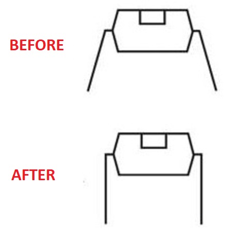
To get the ICs properly mounted in their connectors, the legs have to be bent to an angle of about 90 degrees. Out of the box these legs are angled slightly outwards. Make sure you bend these legs with proper care, as these legs can break easily.
3.4 Placing LED elements
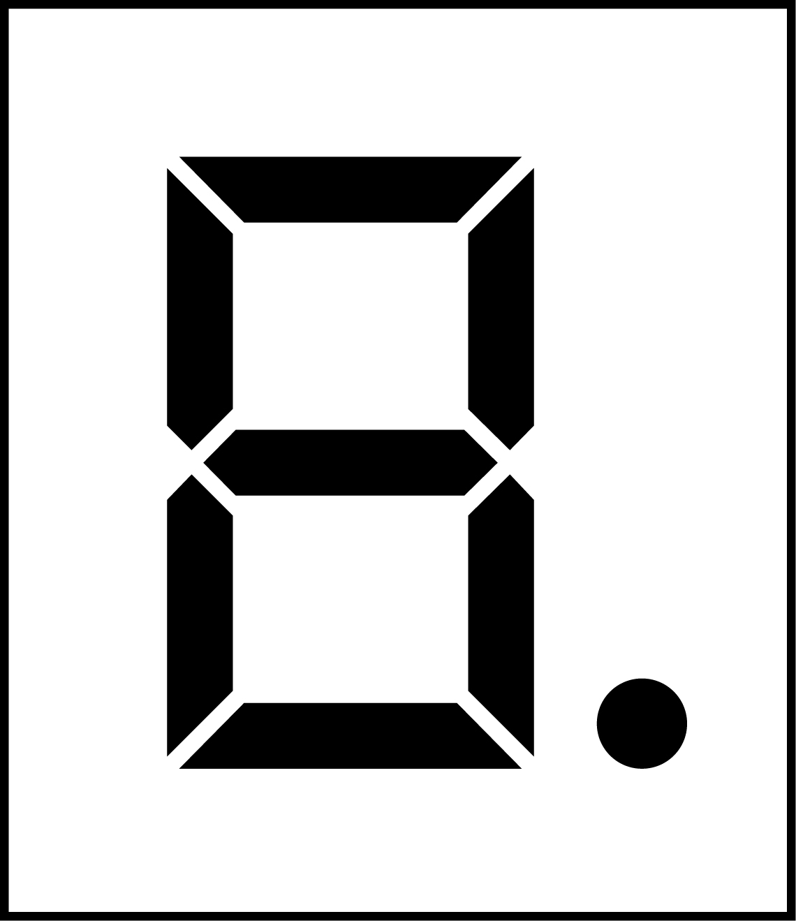
Make sure to remove the protective foil of each of the elements, this can then be placed on the other side of the elements for protection. Make sure the third LED element is placed and soldered upside down (see picture below).
3.5 Polarised foil
The included polarized foil can be used on the LED screen, to improve visibility.
3.6 Assembling the case
Firstly, make sure that the protection foil of the perspex case is removed. After this, the included screws can be used to assemble the case. The sticky brown foil has to be removed on both sides of the perspex. The different sides can be connected to each other by sliding the nut in the slid in the perspex, and use a screw to secure this (see pictures).


4. Clock controls
Although we hope that the assembly of the clock was already a lot of fun, this is not the end of it. The actual clock has a lot of different features which are up to you to discover. As a starter, the side buttons can be used to brighten and dimm the LED backlight and to open the menu. Both buttons can also be used simultaneously. All functions/findings can be shared with other DIYers at the bottom side of this page!
5. Wiring diagram





